Liquid Fill Steadies the Pointer Under Vibration and Pulsation
A 4 inch liquid filled pressure gauge is a mechanical Bourdon tube gauge with an approximately 100 mm dial and damping liquid inside the case. Process pressure enters through the connection and deflects the Bourdon tube. The movement transfers that deflection to the pointer, while glycerin or silicone oil damps motion around the movement and pointer.
The damping effect makes the indication easier to follow when equipment vibration, pressure pulsation, or frequent starts and stops would otherwise make the pointer oscillate. The fill liquid stays in the case and does not normally enter the process pressure path.
Liquid filling does not raise the gauge's static accuracy class. A stable pointer still depends on a suitable pressure range, a compatible connection and wetted material, and protection from pressure conditions beyond the selected gauge's limits.
Choose the Range, Mount, Connection, and Materials Together
The dial diameter answers only the visibility and space question. A complete 4 inch gauge specification also defines the pressure range, scale unit, connection location, thread, wetted parts, temperature conditions, and fill liquid.
Compare the Two Models
4 Inch Liquid Filled Pressure Gauge Models
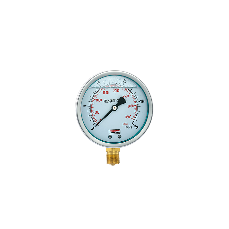
The YN-100 combines a 100 mm dial with a bottom process connection. It mounts directly above a compatible pressure takeoff when the pipe connection approaches the gauge from below.
- Dial100 mm, 4-inch class
- Process connection positionbottom entry
- Installationdirect mounting above the pressure takeoff
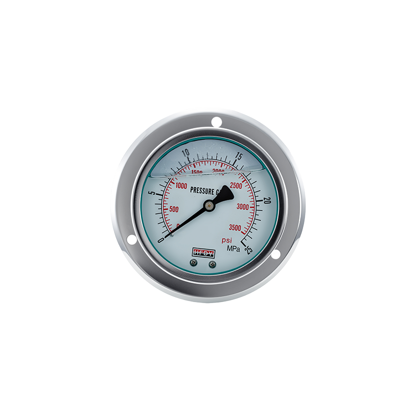
The YN-100ZT places the process connection behind the 100 mm dial and adds a front flange for mounting on an equipment face or panel. The front-mounted dial remains visible while the connection and supporting installation sit behind the panel.
- Dial100 mm, 4-inch class
- Process connection positionrear entry
- Installationfront-flange mounting on an equipment face or panel
Shared Specifications and Available Pressure Ranges
YN-100 and YN-100ZT share the same 100 mm dial size and accuracy class. Their main difference is the way the gauge connects to and mounts on the equipment.
Specify the desired dial unit as part of the order. The selected scale should match the units used in operating procedures and on the connected equipment so operators can read the pressure without conversion.
Connection size and thread are separate from the 4 inch dial size. Include the full equipment-side connection marking with your inquiry so the quoted gauge can be matched to the correct thread and sealing method.
Install the Connection Without Loading the Gauge Case
Confirm the complete thread designation and sealing method before installation. A similar outside diameter does not make NPT, BSP, and metric threads compatible. Use only adapters whose pressure, temperature, and material ratings suit the full connection chain.
Isolate and depressurize the system before fitting the gauge. Apply installation torque to the wrench flats on the process connection. Do not tighten the gauge by turning the case, bezel, window, or front flange. Support the pipework so the gauge connection does not carry unwanted piping load or alignment force.
For the YN-100ZT, confirm the panel opening, flange attachment points, rear clearance, connection access, and reading direction before the panel is prepared. Final mounting dimensions should be approved against the ordered configuration.
Bring pressure into the gauge gradually and confirm that the pointer returns and responds smoothly. During service, inspect the window, case, connection, and surrounding pipework for damage, leakage, loosening, or an unstable indication. Isolate and depressurize the system before removing or replacing the gauge.
Send Your Gauge Specification
 Dypressuregauge