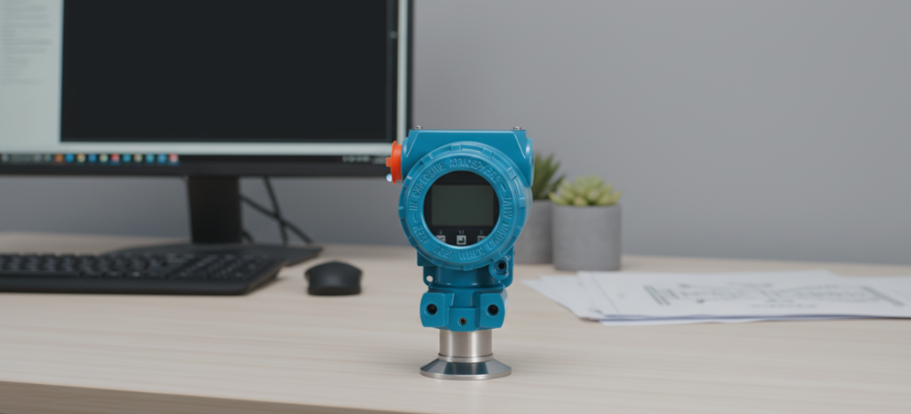
How Do Differential Pressure Transmitters Work
The differential pressure transmitter is essentially a “pressure difference comparator”. It measures the pressure difference between the two ports (high pressure end and low pressure end), and then converts this tiny physical force into an electronic signal commonly used in our industrial field, such as a 4-20mA current loop or a HART digital signal. Inside the transmitter, the core principle is not complicated, but it is this sophisticated transformation process that ensures that it can accurately convey the fluctuations of the physical world to the control system.
How Does Stress Change Signals
To understand what’s going on inside the device, we have to start with the series of physical reactions inside the sensing capsule.
1. Double Port Interface: Looking For Pressure Difference
Each differential pressure transmitter is equipped with two input ports: high pressure side (HP) and low pressure side (LP). The design logic of the device is to compare the differences between these two points. By capturing the “delta” (difference) between these two points, the transmitter can accurately determine the pressure drop in the process. In many cases, the measurement deviation of the equipment does not come from the transmitter itself, but the installation position is not symmetrical enough to collect the two pressure points.
2. Isolation And Liquid Transfer
In the port position, the isolation diaphragm acts as a barrier, which is responsible for isolating the process medium from the internal structure. Once pressure is applied to the diaphragm, it deforms. This displacement is transmitted by the filling fluid (usually silicone oil or inert fluorocarbon oil). The filling liquid is sealed in the capillary channel inside the sensor module. It is like a “mechanical bridge”, isolating the harsh external conditions from the sensitive internal electronic components. This is why some transmitters can withstand high temperatures and pressures.
3. Sensing Element: Capacitive Vs. Piezoresistive
The filling fluid squeezes the main sensing element, and here is the key to converting physical forces into electrical signals:
- Capacitive sensor: This design will place a sensing diaphragm between two capacitive plates. When the pressure difference causes a slight displacement of the diaphragm, the capacitance value will change. This kind of sensor is usually more stable when dealing with small pressure fluctuations over a long period of time.
- Piezoresistive sensor: This is made using a silicon strain gauge bridge. When the pressure changes, the resistance value of the silicon element will change in proportion, thus outputting a clear electrical signal.
Signal Processing: Making Raw Data “Available”
The sensor senses the displacement, but this is only the first step. The original signal is far from the industrial control system, it needs further processing by the “transmitter brain.
Linearization And Calibration
The onboard electronic system runs a set of mathematical algorithms to linearize the raw data. This is like correcting the data to eliminate the effects of ambient temperature fluctuations or static pressure to ensure that the output values truly reflect the process variables.
Output Protocol
Finally, the processed values are converted into standard signals that can be read by the distributed control system (DCS) or programmable logic controller (PLC). The reason why the 4-20mA current loop is still the industry standard is because its stability and anti-interference ability are really reassuring. Of course, most modern transmitters support the HART protocol, which allows us to overlay digital communication onto analog signals, enabling remote diagnostics and configuration, saving a lot of time spent climbing ladders to the field.
Significance In Industrial Applications
Why does industrial automation rely so much on differential pressure transmitters? After all, they are the “eyes” of automation systems “. By interpreting this differential pressure data, engineers can derive a number of key process variables:
- Flow: By measuring the pressure drop on both sides of the orifice or venturi, the flow rate of the fluid can be calculated.
- Level: In a pressurized vessel, the transmitter measures the hydrostatic head to provide very accurate level data.
- Filter status: Monitoring the pressure difference between the two ends of the filter is the fastest way to judge whether the filter element is blocked. Once the pressure difference exceeds the limit, the system will give an early warning.
The differential pressure transmitter converts the pressure of the physical world into an electronic signal that is common to industry. This seemingly inconspicuous conversion actually constitutes the cornerstone of the safe and efficient operation of modern complex process environments.
Author: Mark Thompson
I’m a senior instrumentation and control engineer with over 11 years of hands-on experience in industrial automation. Throughout my career, I’ve specialized in the installation, calibration, and troubleshooting of complex process measurement systems. I am passionate about demystifying industrial hardware and sharing practical, field-tested insights to help fellow engineers optimize their control systems and ensure safe, efficient plant operations.
The prev: How Does A Thermometer WorkThe next: How Does A Pressure Gauge Work