 Dypressuregauge
What Is A Bourdon Tube Pressure Gauge? How It Works
Bourdon tube pressure gauge is the 1 kind of purely mechanical measuring equipment. Its core is 1 flattened bent metal tube, which can directly convert the pressure of fluid or gas into an intuitive reading on the dial. When the medium enters this elbow with pressure, the metal pipe will instinctively try to “straighten”. This tiny deformation will drive the internal gear mechanism and push the pointer across the dial with a scale to accurately display the pressure value of PSI or Bar (bar). The whole process does not require any external power supply or digital sensors, and the readings are still accurate and reliable.
But there is a thorny problem in reality: up to 80% of the early failures of Bourdon tube pressure gauges occur within the first 3 months of installation. The root cause often lies in how the internal linkage responds to system pulses-a detail that is easily overlooked in most industrial purchases. Next, we might as well put aside those obscure physical formulas and directly disassemble its mechanical principles and common failure points to see what kind of configuration is needed to keep your production line from falling off the chain.
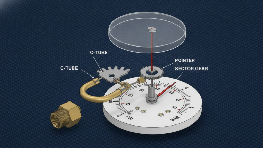
The C.G.P. Framework: How Does A Bourdon Tube Work?
Most textbooks talk too much about mechanical pressure measurement. When we train junior maintenance mechanics, we usually use a set of “C.G.P. mechanical conversion models” (ie Curve bends, Gear gears, Pointer pointers) to deconstruct in the vernacular. As long as the 3 step, you can understand how the pressure becomes a dial reading.
Step 1: Bend the pipe (from pressure to physical displacement)
The fluid or gas is poured from the interface at the bottom of the meter and directly into the hollow “C” type metal tube inside. Because the cross-section of the tube is a flattened oval, internal pressure will desperately press the wall of the tube, forcing the oval to bulge and round. Once the cross-section is rounded, the entire C- tube will have a slight “straightening” tendency. The greater the pressure, the more pronounced the magnitude of straightening.
The second step: gear (enlarge small action)
The straightening range of the tube is actually very small, and the tip of the closed tube moves a few millimeters. This displacement cannot be seen by the naked eye alone. Therefore, the tip of the tube is connected to 1 mechanical connecting rod, and the other end of the connecting rod is directly hung with a sector gear (a toothed arc-shaped metal sheet). As long as the tip of the pipe moves slightly, the connecting rod will be pulled and turn with the sector gear.
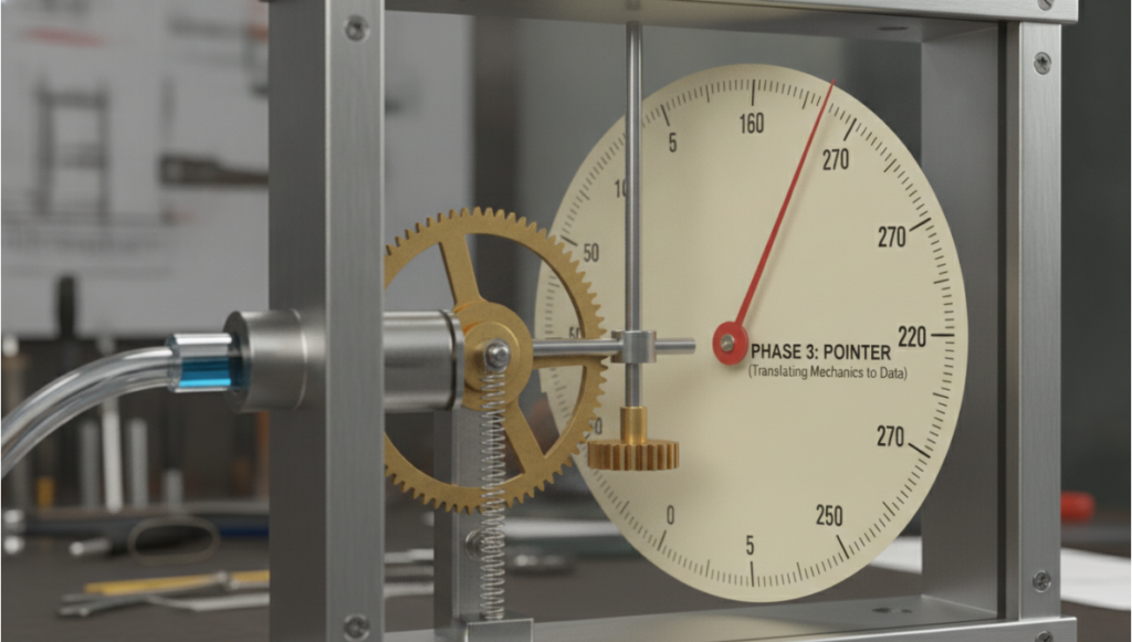
Step 3: Pointer (turn mechanical action into data)
The teeth of the sector gear just bite into a small gear on the center shaft of the dial pointer. As a result, the only 2mm pulling force at the tip of the pipe was instantly enlarged and directly turned into a magnificent 270-degree swing of the pointer on the dial. There is also 1 hairspring inside, which is specially used to maintain the slight tension between the gears, eliminate the gear gap, and ensure that as long as the system is 1 relieved, the pointer can return to zero cleanly and immediately.
Three Branches Of Bourdon Tube: C Type, Coil Spring Type And Spiral Tube Type
The standard C- tube is sufficient to handle 90% of the routine work in the factory. However, if you encounter high-pressure hydraulic lines or special gas systems, you need to change the internal geometry to withstand metal fatigue.
Type C Bearden tubes: Built for the standard pressure range (up to 1,000 PSI). The tube is bent into an arc of about 250 degrees. Dealing with general water, air and light oil systems is definitely a good hand.
Spiral: The metal tube is rolled into a flat “mosquito-like”. The subtlety of this design is that it can produce a large tip displacement, without the need for complex amplification gear sets. In the strong oscillation environment where traditional gears are shattered in minutes, engineers tend to use it decisively.
Helical Bourdon tube (Helical): The tube is wound three-dimensionally like a spring. It can withstand extreme high pressure impacts up to 10,000 PSI without permanent metal deformation. It is the standard part used in heavy hydraulic machinery and oil drilling blowout preventers.
| Tube Type | Best For (Pressure Range) | Pros | Cons |
| C-Type | Standard pressure ranges (up to 1,000 PSI). General water, air, and light oil. | Covers 90% of basic factory applications; excellent and reliable for general, everyday use. | Prone to metal fatigue in high-pressure hydraulic lines or specialty gas systems; requires complex amplifying gears. |
| Spiral | Heavy-vibration environments. | Creates more tip movement; eliminates the need for complex amplifying gears; won’t strip apart under heavy vibration. | Not specifically designed to handle extreme high-pressure spikes compared to helical designs. |
| Helical | Extreme high-pressure spikes (up to 10,000 PSI). Heavy hydraulic machinery & oil rigs. | Can handle extreme pressure spikes without permanent metal deformation. | Over-engineered for standard or basic low-pressure factory applications. |
First Line Measured Data: Why Can’t Connecting Rod Survive 90 Days?
We did internal tests on 500 high-frequency hydraulic lines, and the results tore apart a fig leaf about material limits. At that time, we were in a high pulse press, the ordinary dry brass Bourdon tube pressure gauge, and liquid filled 316L stainless steel pressure gauge next to the installed together for comparison.
The result? The brass table lives less than 14 days on average. The sharp pressure fluctuation made the brass pinion tremble wildly, and it didn’t take long for the teeth to be ground flat. At this time, the tube was clearly holding high pressure, but the watch needle fell directly to zero-this is definitely a heavy safety hazard.
On the other hand, those stainless steel watches filled with liquid lasted 18 months. The glycerin poured into the watch case is like a shock absorber, not only holding down the jumping pointer, but also lubricating the metal gear.
The core conclusion is very simple: as long as there is a reciprocating pump in the system, the valve will open and close in a hurry, or the surrounding environment vibrates greatly, don’t touch the dry Bourdon watch made of brass inside.
Guide To Avoid Pits: Buy Bourdon Tube And Don’t Step On 3 Thunder
When purchasing teams buy pressure gauges, they often only focus on the size of the threaded interface and the maximum range of the dial. This directly dug a big hole for future maintenance. If you want the production line to be peaceful, you must avoid these 3 specific traps:
1. “Dead Water Section” Icing Trap
In winter, an ordinary Borden watch is installed on an outdoor water pipe. Water poured into the Bourdon tube will not circulate, which forms a period of “stagnant water”. As the temperature drops 1, the water held in the tube 1 freeze and expand, which can crack the metal tube on the spot. If it is easy to freeze the outdoor environment, honest practical diaphragm seal pressure gauge.
2. Mistake of Full Scale (100%)
If the Bourdon tube is pushed to its limit every day, its elastic memory will be wasted. If the normal pressure of your system is 100 PSI, don’t buy a watch whose full scale is just 100 PSI, just buy a 200 PSI. Remember an iron rule: normal working pressure must always fall in the 1/3 interval in the middle of the dial (almost the 10 o’clock to 2 o’clock position on the dial).
3. Ignore the “water hammer effect”
When the solenoid valve is closed instantly, a huge pressure shock wave (water hammer) will be set off in the pipeline. This violent wave can tear a standard Bourdon tube in an instant. In order to protect your equipment, it is wise to spend a little money to add a “buffer” (damper) between the pipeline and the instrument to remove the fatal instantaneous impact force.
FAQs
Q: What is the biggest difference between Bourdon tube and diaphragm pressure gauge?
A: The Bourdon tube relies on the principle of bending metal tubes to straighten under pressure, which is very suitable for clean gases and liquids. The diaphragm surface is a layer of flexible metal diaphragm that can be bulged under pressure. If you encounter extremely viscous liquid, sludge or corrosive chemicals that are easy to block the hollow pipe, the diaphragm surface is definitely a better choice
Q: Bourdon tube pressure gauge can measure vacuum (negative pressure)?
A: No problem at all. When measuring the vacuum, the pressure in the tube is lower than the atmospheric pressure, and the Bourdon tube will not straighten out, but will roll inward more tightly. At this time, the internal linkage mechanism is like a reverse gear, pulling the pointer to the negative pressure scale.
Q: Why are some Borden watches filled with liquid?
Answer: The manufacturer fills the case with glycerin or silicone oil to deal with severe vibration and pressure pulses. This layer of liquid can hold down the pointer to prevent it from fluttering, ensuring that you can see the reading clearly, and at the same time, it can also oil the internal gears to prevent them from premature wear and strike.
Q: Does the Bourdon tube pressure gauge need to be plugged in?
answer: pure mechanical borden meter does not need a penny of electricity. Because of this, whether it is in the explosion-proof area (ATEX dangerous area), or the entire plant power outage, it is the most reliable man.
Q: How often does this watch need to be calibrated?
Answer: If it is the core industrial process, the technician usually takes the static pressure gauge (piston pressure gauge) to calibrate it every 6 to 12 months. However, for those auxiliary pipelines that are not so important (such as ordinary water pipes in the factory), everyone basically uses them to completely break down and replace them directly. After all, buying a new watch is often much more cost-effective than sending it to a laboratory for calibration.