 Dypressuregauge

A Manifold Pressure Gauge Is Designed To Do What?
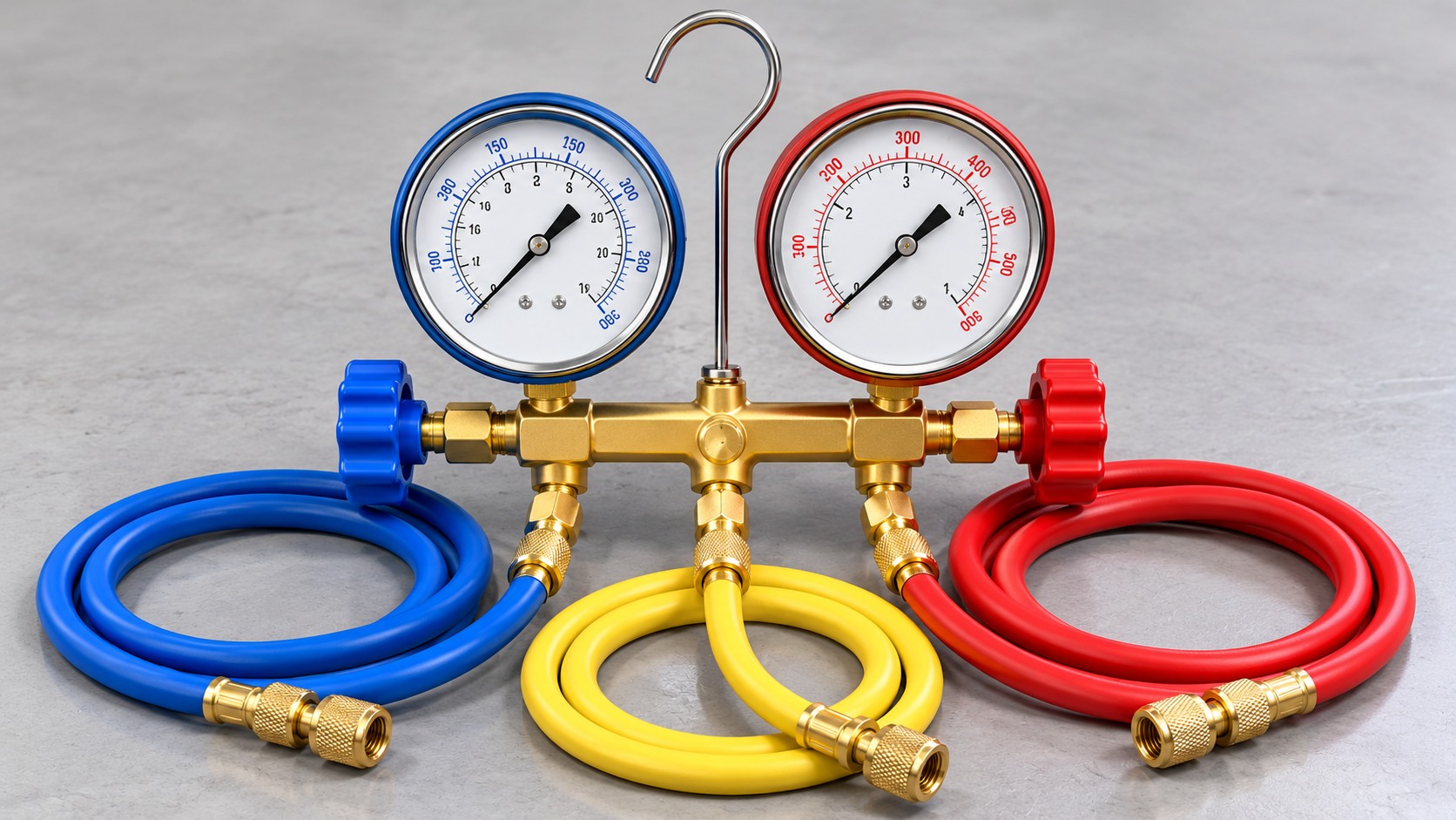
When you connect the refrigerant pressure gauge assembly to the air conditioner, you are actually seeing two sides of the same system. The two high and low voltage pointers can intuitively tell you the current real situation of the system maintenance port. However, the function of a table group is far more than just a display. It integrates these pressure data and maintenance interfaces through the middle valve body, allowing the masters to have a safe and controllable channel to evacuate, recover or add refrigerant to the system. But let me be clear first: just by hanging a watch, it is impossible to directly determine which part is broken or whether the refrigerant is accurate.
Secrets On The Dial
If you are using the most common traditional mechanical watch, the low-pressure side watch is called the “connecting watch” within the row. What does that mean? It can not only measure positive pressure above normal atmospheric pressure, but the pointer can also go down to measure a rough vacuum. As for the high-pressure gauge, it is designed purely to carry the high pressure in the discharge pipeline.
The color scheme that everyone is most familiar with is definitely “blue, low, red, high”. This is just an industry practice for ease of work. The color itself cannot represent how much pressure the pipe can withstand, nor can it determine the actual function of the interface. Before taking over the equipment, be sure to confirm the equipment’s interface label, range, pipe pressure resistance value, and current operating mode. Especially when repairing heat pumps (heating and cooling air conditioners), the high and low pressures in the pipeline will be directly reversed from cooling to heating.
How To Operate The Valves In The Table Group
The most commonly used type is the three-tube table set: the blue tube is connected to the low pressure, the red tube is connected to the high pressure, and there is usually a yellow maintenance tube in the middle. The two hand valves on the table set are used to control on and off——Open the valve, and the refrigerant can enter and exit along the middle pipe, which is usually connected to a vacuum pump, recycling machine or refrigerant tank. Sometimes a four-hole gauge is used, which is nothing more than multiple channels, which can reduce the trouble of removing the cannula when working.
If you just want to measure the operating pressure, then these two hand valves must be shut off. In this way, the two tables can display their respective pressures obediently, without stringing high and low pressures together, and without letting the refrigerant run away along the yellow tube in the middle. Therefore, you must follow the specifications and instructions.
The Basic Law Is Necessary To Understand The Pressure
Just looking at the pressure value is not very meaningful, and talking about pressure without considering the working conditions is not accurate at all. You need to know what refrigerant the machine is using, whether it is currently running, what mode it is running in, and also combine the ambient temperature indoors and outdoors. Even insufficient air volume, poor water flow, excessive heat load, or a single action of the control panel will cause high and low pressures to run up and down. Never use other machines or other operating conditions to apply “standard pressure” as an absolute diagnostic standard.
Take a closer look at the mechanical dial; there are usually several turns of temperature scale next to the pressure scale. That’s the “saturation temperature”—— corresponding to a certain type of refrigerant. Remember, this is definitely not the actual temperature of the copper pipe right now. If the refrigerant used in the machine happens to be unlabeled on your dial, the pressure scale is passable, but this lap of temperature scale is completely useless.
To really calculate superheat or subcooling, you have to honestly take a temperature probe and tie it to the pipe to measure the actual pipe temperature, and then compare it with the PT (temperature-pressure) meter to calculate. If you encounter mixed refrigerants that are currently experiencing “temperature slip”, you must also distinguish between bubble points and dew points. To put it bluntly: Don’t rush to add fluorine just by looking at the pressure gauge; check honestly according to the manufacturer’s specifications.
Clarify The Tool’s Upper Limit
Finally, work to the upper limit of the tools at hand. That rough negative pressure scale on the low-pressure gauge is fine to see if the pressure is dropping, but it’s definitely not accurate enough to prove that you’ve pumped the system into a thoroughly dry deep vacuum. To meet the standards, a dedicated high-precision electronic vacuum gauge (micron meter) is required. Similarly, the table set cannot replace the refrigerant recovery machine, vacuum pump, and dedicated fluorinated electronic scale.
Before each takeover, it’s best to check the full set of things: pipes, watch bodies, valves, seals, and various joints. The pressure resistance limit of the entire table set depends on the weakest part at your head. Make sure your tube can withstand the pressure of the current machine’s refrigerant and the refrigeration oil; just looking at it with a “refrigerator tube” printed on it is not enough. Keep the joint clean. Remember to drain (exhaust) the air in the pipe before putting the refrigerant in. After the work is done, properly dispose of the remaining refrigerant in the pipe according to the rules.
In short, you can think of the refrigerant meter group as a window through which you observe the closed system of your equipment. It allows you to see the pressure at key points and provides an operational interface. However, these pressure figures are only considered a truly reliable diagnostic basis when you combine the refrigerant type, ambient temperature, operating status, and actual pipe temperature.