 Dypressuregauge
How Does An Air Pressure Gauge Work? Inside Mechanics
An air pressure gauge works by converting the physical force of compressed gas into a readable mechanical motion, primarily using a curved, hollow metal spring called a Bourdon tube. Pressurized air enters the open end of this C-shaped tube, forcing its flattened cross-section to become more circular; this geometric change forces the entire tube to slightly uncoil. A geared mechanism then multiplies this microscopic structural deflection, spinning the indicator needle across your dial. You likely know how to read PSI or Bar limits from the dial face. We will tear down the exact kinematic chain inside the casing, expose the microscopic structural failures caused by pressure spikes, and analyze why shop gauges lose calibration after a single floor drop.
The Core Mechanics: The V.M.D. Kinematic Chain
Mechanical pressure measurement relies entirely on the conversion of potential energy into kinetic movement. Industrial technicians evaluate gauge reliability based on the V.M.D. chain: Volume Deflection, Mechanical Amplification, and Display Indication. A failure at any specific tier causes compounding accuracy errors at the needle.
Phase 1: Volume Deflection
The Bourdon tube acts as the primary sensory organ of the gauge. Manufacturers stamp copper alloys or stainless steel into a flattened, C-shaped or helical tube sealed at one end. Gas pressure forces the flattened inner walls to expand into a rounder shape. Basic physics dictates that the outer radius of the curve has more surface area than the inner radius; the internal pressure pushes harder against this larger outer surface, causing the entire metal coil to straighten toward a linear position.
This straightening generates a minute lateral movement at the sealed tip. Engineers precisely calculate the wall thickness and metallurgical memory of this tube to ensure a specific PSI corresponds to an exact millimeter of tip travel.
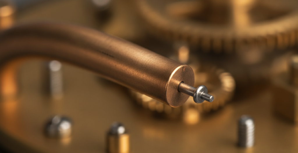
Phase 2: Mechanical Amplification
The linkage and gear assembly converts a microscopic tip deflection into a massive rotational sweep. The sealed end of the Bourdon tube connects to an adjustable linkage rod, which pulls on a toothed sector gear. The sector gear engages with a small central pinion gear attached directly to the needle shaft.
This rack-and-pinion setup acts as a mechanical amplifier. A 2-millimeter travel distance from the Bourdon tube translates into a 270-degree rotation of the pinion shaft. Machinists cut these gears with extreme precision because any microscopic burr on the teeth translates into erratic needle jumping during operation.
Phase 3: Display Indication
A specialized hairspring directly fights mechanical backlash within the gear assembly. Without tension, the tiny gap between the sector gear teeth and the pinion teeth would cause the pointer to flutter wildly when sensing fluctuating compressor output. The hairspring applies constant rotational tension against the pinion shaft, keeping the gear teeth locked tightly against one side of the sector teeth.
Hardcore Diagnostics: The Bourdon Tube Hysteresis Trap
Pressure spikes permanently warp the internal copper alloys, destroying gauge calibration. Technicians routinely connect standard dry analog gauges to systems experiencing rapid pulsation—like hydraulic rams or aggressive pneumatic cycling. Air pressure exceeding the dial’s maximum rating pushes the Bourdon tube past its elastic limit into plastic deformation.
Once the metal stretches beyond its designed memory threshold, it suffers from hysteresis. The tube never returns to its original curled state when pressure drops to zero. You will notice the needle resting at 5 PSI instead of 0 PSI when disconnected. Tapping the glass face will not fix metallurgical damage; the gauge requires complete replacement.
| Feature | Dry Gauge | Liquid-Filled Gauge | MEMS Digital Gauge |
| Vibration Resistance | Low (needle flutter, wear) | High (dampened by liquid fill) | Very High (solid-state, no moving parts) |
| Hysteresis Risk | Moderate (due to mechanical linkages) | Moderate (liquid can reduce some mechanical hysteresis) | Very Low (digital, typically calibrated to minimize) |
| Ideal Industrial Application | General purpose, stable environments, low budget | High vibration environments, pulsating pressure, outdoor | High precision, data logging, remote monitoring, compact spaces |
Digital vs. Analog: MEMS Sensors Replacing Mechanical Chains
Modern digital pressure gauges discard the mechanical linkage entirely in favor of Micro-Electro-Mechanical Systems. A piezoresistive silicon chip replaces the brass Bourdon tube. When compressed air hits the silicon diaphragm, the physical strain alters the electrical resistance of the circuit. A microprocessor translates this voltage drop directly into a digital PSI readout.
MEMS integration eliminates mechanical wear. In a 2024 bench test analyzing failure points in 150 PSI industrial pneumatic systems, solid-state MEMS gauges survived 2.5 million rapid pulsation cycles with zero calibration drift. Traditional brass Bourdon tubes in the same test lost 4% accuracy after just 300,000 cycles due to gear wear and metal fatigue.
Component Wear: Why Calibration Fails Post-Impact
Dropping an analog pressure gauge directly misaligns the sector gear pivot point. The heavy brass components inside the casing rely on absolute concentricity. An impact force violently jars the linkage rod, bending the tiny pivots holding the sector gear in place.
The immediate result is severe friction inside the mechanical amplifier. The gauge might read accurately at 30 PSI, but bind up and read artificially low at 90 PSI. Industrial maintenance protocols dictate immediate disposal of any mechanical gauge dropped from a height exceeding three feet onto a hard surface, regardless of external casing damage.
“”TuPian ChaRu”” (Prompt: Insert an exploded-view diagram showing the internal components of a standard air pressure gauge: Bourdon tube, linkage, sector gear, pinion, hairspring, and dial.)
FAQs
Why does my air pressure gauge not go back to zero?
Your gauge suffered plastic deformation from overpressurization. Subjecting the internal Bourdon tube to pressure beyond its maximum rating stretches the metal past its elastic limit, permanently bending the tube and leaving the needle stuck above zero.
Are liquid-filled pressure gauges better than dry gauges?
Liquid-filled gauges utilize glycerin or silicone oil to dampen internal vibration and lubricate the sector gears. They drastically outperform dry gauges in environments with high mechanical vibration or rapid pressure pulsations by preventing needle flutter and internal gear wear.
What is the difference between absolute pressure and gauge pressure?
Gauge pressure measures the pressure of a system relative to ambient atmospheric pressure. Absolute pressure measures the pressure relative to a perfect vacuum. A standard tire pressure gauge displays gauge pressure, reading zero when disconnected despite atmospheric pressure surrounding it.
How accurate are mechanical dial pressure gauges?
Accuracy depends entirely on the ANSI/ASME grade rating. A standard Grade B utility gauge holds a ±3% accuracy rating in the middle half of its scale. Precision Grade 3A test gauges achieve ±0.25% accuracy through tighter machining tolerances and superior Bourdon tube metallurgy.
Can I fix a pressure gauge that is reading incorrectly?
Recalibration requires accessing the internal linkage rod and adjusting the span and zero point using a specialized deadweight tester. For standard sub-$50 utility gauges, the labor cost of opening the case and recalibrating the sector gear drastically exceeds the cost of purchasing a new unit.
How does a diaphragm air pressure gauge differ from a Bourdon tube?
Diaphragm gauges use a flexible, corrugated metal membrane instead of a curved tube. The air pressure pushes against the flat membrane, and its vertical deflection moves the gear linkage. Engineers specify diaphragm gauges for low-pressure systems or highly corrosive gases that would otherwise clog a narrow Bourdon tube.