 Dypressuregauge
What Is a Supply Pressure Gauge? Core Functions Revealed
The so-called gas pressure gauge is a measuring instrument installed at the forefront (upstream) of a fluid or pneumatic system. Its task is simple: stare at the original “gross pressure” coming from the air compressor or the main gas tank “. Before any pressure relief valve intervenes and changes the airflow, you have to look at this dial to make sure the machine is full enough power. Many novices think the system is healthy as long as they see the pointer pointing to “100 PSI. In practice, however, such static readings tend to mask the deadliest hole in pneumatic equipment-the lack of dynamic pressure. Today, we will thoroughly dismantle how this small instrument determines the life and death of the machine, and by the way, we will teach you some diagnostic skills of the old fitter at the bottom of the box.
S.D.A. Piping Model: Supply And Demand Meeting Point
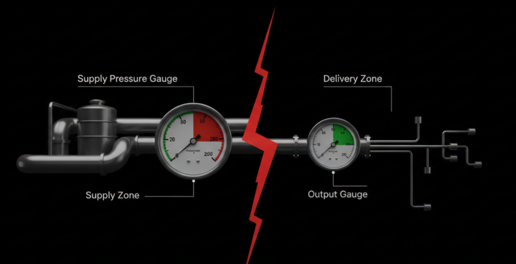
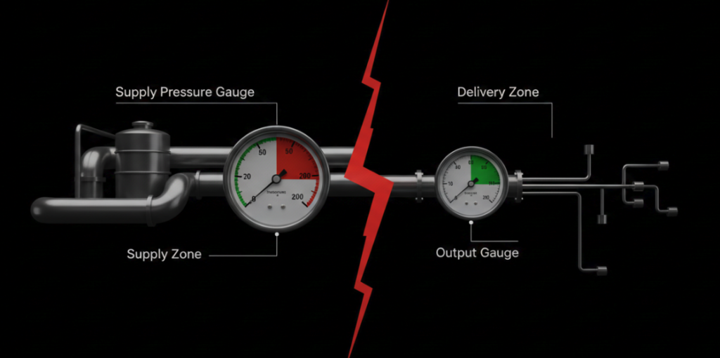
If you want to avoid detours and messing around, you must first understand the hierarchical relationship of the pipeline. The S.D.A. piping model divides any pneumatic circuit into 3 zones: supply (Supply), output (Delivery), and execution (Actuation).
The “site” of the gas supply pressure gauge is only in the “gas supply area”. It always sits upstream of the gas treatment trio (FRL). This watch is used to score the main air compressor in the workshop and the pipes connecting the machine. If the pressure here is off the chain, your machine is “starving” from the source.
The output area uses a completely different 1 type of meter, called “output pressure gauge”. This watch is installed behind the pressure reducing valve and shows the working pressure after depressurization. If you mix up these two watches, it will definitely lead to disaster. Remember: never look at the “air supply meter” to adjust the running speed of the machine.
What Is The Use Of Gas Pressure Gauges? Three Core Functions
1. The “polygraph” of the health status of the gas source”
The air supply pressure gauge is like a polygraph in the system. It is clear how much original pressure the air compressor has delivered to the machine and whether there is any air leakage in the plant pipeline. If the machine is lying down, you should count on this reading to judge whether the local hardware is broken or the air pressure of the whole factory is not enough.
2. Find out the invisible “intestinal obstruction” in the pipeline”
Before the complete shutdown, this watch can help you find hidden dangers in advance. When the machine is running normally, if the air supply pressure suddenly plummets, it can be immediately concluded that either the main filter is blocked or the upstream air pipe is flattened. Veteran at the scene usually stares at the rebound speed of the pointer after the machine runs for a cycle, so as to evaluate whether the intake pipe is smooth or not.
3. Delineation of safety red lines
This watch sets an absolute pressure ceiling for the components in your area. You have to look at the gas supply meter to make sure that the untreated raw gas does not exceed the burst limit of the downstream pressure reducing valve and plastic gas pipe. If you don’t even look at the gas supply meter, directly connect the high-pressure gas source 200 PSI to the machine with the highest resistance of only 120 PSI, the collapse of the sealing ring is light, and even serious safety accidents will occur.
Expert Field Guide: Avoid These 3 Novice Pits
Recently, we disassembled 150 scrapped industrial pneumatic panels and found that 68% of the so-called “pressure reducing valve failures” were actually misdiagnosed as blocked air supply lines. To put it bluntly, the novice will not look at the watch. Don’t step on these 3 minefields:
Pit 1: Fool by the illusion of “static pressure”
Static pressure is meaningless to a working machine. You have to read the gas supply meter when the machine cylinder is banging, not when it’s stopped. Some watches look perfect at 90 PSI when they are on standby. When they are turned on, they drop to 40 PSI instantly because the air supply pipe is folded. Remember, the diagnosis always depends on the dynamic pressure drop.
Pit 2: Ignore the “double range” rule
If you buy a watch with a maximum scale just equal to your system pressure, then I can guarantee that the Bourdon tube (spring tube) inside will not last for a few months. Always running at full load against the physical limit of the instrument, the C- tube inside will soon deform and be completely inaccurate. When buying a watch, be sure to let your daily air supply pressure fall right in the middle of the dial. For example, 100 the PSI air supply line, you have to match 200 PSI meter.
Pit 3: Indiscriminate thread connection leads to catastrophe
Hard screw the NPT (US standard taper pipe thread) meter into the BSPT (British standard taper pipe thread) interface, and waste the bus plate every minute. These two threads look like twins to the naked eye, but the pitch angle is completely different. If you screw it in forcibly, micro cracks will occur inside the metal, and the high-pressure gas supply will inevitably leak. Before doing it, be sure to see the thread specification of laser marking at the instrument joint.
| Feature | Supply Gauge Specifications | Output Gauge Specifications |
| Location | Upstream of the primary process or equipment. | Downstream of the primary process or equipment. |
| Primary Target | Monitor incoming pressure/flow from the source. | Monitor outgoing pressure/flow to the next stage/system. |
| Normal Fluctuation Level | Typically less stable, can show variations due to source fluctuations. | Generally more stable, reflecting process control effectiveness. |
| Failure Symptoms | Inconsistent incoming material/energy flow, upstream equipment malfunction, line blockages. | Inconsistent product quality, downstream equipment malfunction, system performance degradation. |
2026 Industry Wind Direction: Mechanical Pointer Table Exit
In the modern high-speed manufacturing industry, the traditional mechanical Bourdon tube pressure gauge is facing elimination. Today’s new pneumatic equipment, has long been occupied by the IO-Link digital gas pressure gauge. These digital sensors can be real-time millisecond pressure drop data directly to the PLC.
The maintenance team takes this data for predictive diagnostics. A IO-Link air supply meter can keep a close eye on the performance decay track of the main air compressor for half a year. Now change the filter, everyone is looking at the digital trend chart, instead of waiting for the operator to complain that the cylinder movement is slowing down before going to overhaul.
FAQs
What is the difference between supply pressure and output pressure?
The air supply pressure is the “original gas” coming in from the main air compressor, and the force is original and uncontrolled. The output pressure is the reduced pressure specially used for mechanical work after being treated by the pressure reducing valve. The supply pressure must always be higher than the output pressure.
How should the air supply pressure gauge read?
The outer ring of the dial reads PSI (pounds per square inch) and the inner ring reads Bar or MPa. Key points: You must read the readings when the machine is running and cycling, so that you can catch the real dynamic air supply pressure.
Why does the machine clearly have gas, but the gas supply meter shows zero?
Either the Bauden tube in the instrument burst, or the small hole in the instrument connector was blocked by air compressor oil and impurities. In this case, you have to unscrew the watch and check the brass air inlet at the bottom. If the hole is not blocked, the watch will be completely scrapped and can only be replaced.
Can the air supply meter be dressed upside down?
Yes. Mechanical pressure gauges rely on internal pressure expansion, not gravity tube. You can do whatever you want, as long as the operator can see the dial clearly and the thread sealant is applied in place.
Why do the hands of the air supply meter jump like crazy?
The wild jump of the pointer indicates that there are extremely violent air flow fluctuations in the air supply pipeline, usually because the pipe is too thin, but too much air must be squeezed in. The solution is to replace a liquid-filled pressure gauge (which is usually glycerin) and use the damping of the liquid to absorb the shock and protect the internal gear.
What position should the air supply pressure gauge be installed in?
Installed directly at the main air inlet of the machine, next to the main stop valve, or next to the 1 stage of the gas treatment triple (FRL). Put it here to accurately measure the most real state of the factory’s raw gas before it enters your machine and is modified.