 Dypressuregauge
What Are The Types Of Pressure Gauges & Core Principles?
Pressure gauges operate on the core principle of elastic deformation—mechanically converting fluid pressure into a readable dial indication. The primary types of pressure gauges include Bourdon tube, diaphragm, bellows, and capsule gauges, each engineered to isolate specific process media from internal gear linkages. Engineers frequently treat these instruments as simple commodity hardware, resulting in a staggering 70% premature failure rate in heavy industrial facilities. We will deconstruct the exact mechanical kinematics of these sensing elements and provide a field-tested engineering framework to eliminate specification errors before commissioning.
What is the Principle of Pressure Gauge? Kinematics Breakdown
Every mechanical pressure gauge relies on Hooke’s Law, translating the applied pressure into a proportional physical displacement within an elastic metallic element. This microscopic movement undergoes mechanical multiplication through a complex linkage system to drive a pointer across a calibrated scale.
Bourdon Tube Mechanics: Radial Expansion
A Bourdon tube functions by forcing a flattened, curved metallic tube to regain its circular cross-section under internal fluid pressure. This physical straightening process produces a minor linear tip travel, typically measuring between 2 to 4 millimeters. A precisely machined sector gear and pinion assembly captures this tiny linear motion and multiplies it into a 270-degree rotary sweep.
Diaphragm Kinematics: Micro-Deflection under Aggressive Media
Diaphragm gauges utilize a concentrically corrugated sheet metal membrane that physically separates the wetted process side from the dry dial mechanism. Fluid pressure pushes against this barrier, causing a vertical deflection. A push-rod transfers this precise lift directly to the gear mechanism. Engineers specify diaphragm mechanisms exclusively when dealing with highly viscous slurries or crystallizing fluids that would instantly plug a standard Bourdon tube.
Bellows Elements: High-Sensitivity for Low Pressures
Bellows operate via a thin-walled, accordion-like metallic cylinder that expands linearly. The immense surface area of the bellows convolutions provides exceptionally high force output per unit of pressure. This geometric advantage allows bellows gauges to detect micro-pressure fluctuations in draft systems or HVAC ducts where a Bourdon tube lacks the necessary mechanical sensitivity to register any movement.
What Are the Types of Pressure Gauges? (Application Specifics)
Industrial categorization extends beyond the internal elastic element; system designers define gauge types based on their external environmental casing and the specific reference pressure they measure.
Liquid-Filled vs. Dry Case Instrumentation
Liquid filling absorbs kinetic energy generated by external machinery. Glycerin or silicone oil injected into the dial case acts as a mechanical shock absorber, dampening pointer flutter caused by heavy pump vibrations. Dry cases suit static, climate-controlled environments like laboratory manifolds. Liquid-filled units physically displace oxygen inside the casing, completely preventing internal lens fogging and protecting the delicate brass gears from atmospheric corrosion.
| Comparison Dimension | Dry Case | Liquid-Filled Case |
| Vibration Tolerance | Low Designed for static environments; lacks a dampening mechanism for kinetic energy. | High Acts as a mechanical shock absorber (via glycerin or silicone oil); dampens pointer flutter caused by heavy pump vibrations. |
| Temperature Range | Stable / Restricted Requires climate-controlled environments to function optimally. | Variable / Wide Tolerates temperature fluctuations well; physically displaces oxygen to completely prevent internal lens fogging. |
| Maintenance Frequency | Higher (in un-controlled areas) Vulnerable to internal lens fogging and atmospheric corrosion of delicate brass gears. | Lower Internal liquid protects delicate brass gears from atmospheric corrosion, extending the instrument’s lifespan. |
| Typical Application | Laboratory Manifolds Static, indoor, climate-controlled environments. | External Machinery & Heavy Pumps Harsh environments with high vibrations, potential corrosion, and fogging risks. |
Absolute, Gauge, and Differential Measurement
Gauge pressure (Pg) devices reference ambient atmospheric pressure, venting their casings to the surrounding air to measure the direct process load. Absolute pressure (Pa) gauges seal a hard vacuum reference chamber behind the sensing element, ensuring accurate readings independent of altitude or severe weather barometric shifts. Differential pressure (DP) gauges utilize opposing pressure chambers separated by a sensing element to calculate the exact pressure drop across filtration systems or restriction orifices.
The “C.O.R.E.” Mechanical Integrity Framework (Expert Model)
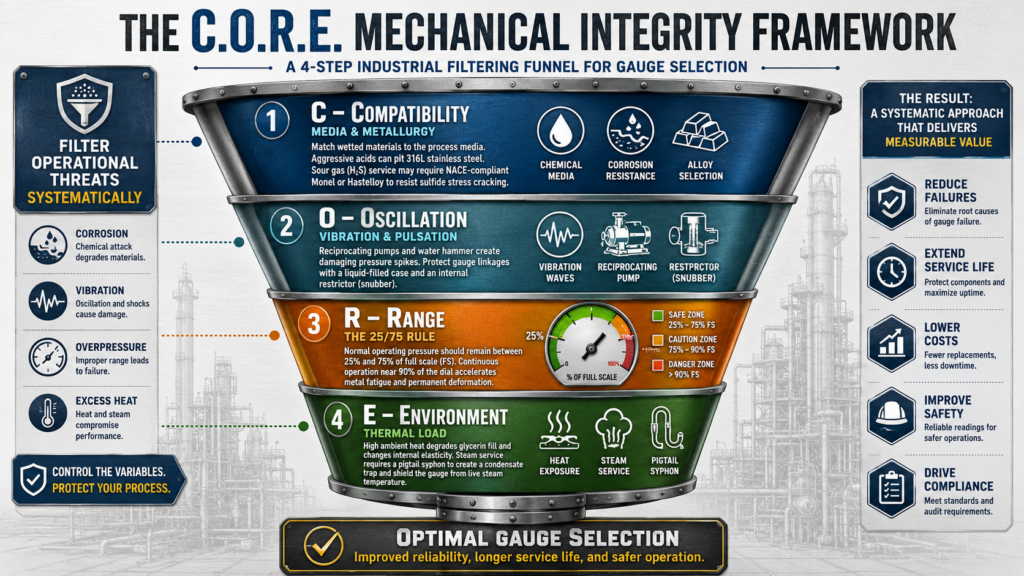
Selecting the correct gauge requires analyzing the destructive forces of the process environment. Based on a decade of post-failure metallurgical analysis, I developed the C.O.R.E. selection matrix to force engineers to evaluate operational threats systematically.
- C – Compatibility (Media & Metallurgy): Direct contact between aggressive acids and 316L Stainless Steel causes rapid pitting. Sour gas (H2S) applications mandate NACE-compliant Monel or Hastelloy wetted parts to prevent sulfide stress cracking.
- O – Oscillation (Vibration & Pulsation): Reciprocating pumps create hydraulic shockwaves (water hammer). Protect the gauge linkages by pairing a liquid-filled case with an internal threaded restrictor (snubber) to throttle the dynamic pressure spikes.
- R – Range (The 25/75 Rule): ASME B40.100 standards dictate that the normal operating system pressure must fall strictly between 25% and 75% of the gauge’s full-scale (FS) range. Operating consistently at 90% of the dial induces premature metal fatigue and plastic deformation of the elastic element.
- E – Environment (Thermal Load): High ambient heat degrades glycerin fill and alters the elasticity modulus of the internal metal. Steam applications require a pigtail syphon tube to create a condensate trap, protecting the gauge internals from direct live steam temperatures.
Field Pitfalls: Why 80% of Gauges Fail Prematurely
Textbook knowledge rarely covers the actual reasons instrumentation breaks down on the factory floor. Plant operators constantly repeat the same specification errors.
Pitfall 1: The “High-Precision” Vibration Trap
Maintenance engineers frequently order Class 0.1% or 0.25% test gauges for vibrating pipework, assuming tighter accuracy translates to better build quality. High-precision mechanical movements rely on razor-thin gear tolerances with zero backlash. Heavy vibration causes these fine teeth to act like miniature milling cutters, shearing each other into brass dust within weeks. Standard duty (Class 2.5%) movements possess the necessary mechanical slack to survive industrial shaking.
Pitfall 2: The Dead-Leg Crystallization Hazard
Designers often install standard threaded pressure snubbers to dampen pulsations on heavy crude or sludge lines. The narrow orifice of the snubber creates a “dead-leg”—an area of zero fluid velocity. Suspended solids instantly drop out of the fluid, crystallizing and plugging the orifice solid within 48 hours. Slurry applications strictly require flush-mounted diaphragm seals with capillary tube extensions to transmit pressure via captive fill fluid, entirely eliminating dead-legs.
2026 Industry Trend: LoRaWAN Hybrid Mechanical Gauges
The industrial sector is aggressively shifting toward hybrid instrumentation that bridges purely mechanical safety with Industrial IoT (IIoT) data collection. Engineers are currently deploying mechanical Bourdon gauges equipped with integrated optical MEMS encoders behind the dial. The elastic element handles the physical pressure measurement—meaning the local visual display functions flawlessly without external power. Simultaneously, the encoder converts the mechanical movement into a digital signal, transmitting real-time telemetry to the control room via low-power LoRaWAN networks. This eliminates the need to choose between traditional mechanical reliability and digital smart-plant integration.
People Also Ask (FAQ)
Q: Can a standard pressure gauge measure negative pressure (vacuum)?
No. A standard gauge reads from zero upwards. Vacuum measurement requires a specific vacuum gauge where the Bourdon tube is configured to contract inward under negative pressure, driving the pointer counter-clockwise from the zero mark. Compound gauges can measure both positive and negative pressure on a single dial.
Q: What causes the pointer on a pressure gauge to stick or freeze?
Pointer freezing usually indicates severe overpressure that pushed the Bourdon tube past its yield point, causing permanent plastic deformation. Alternatively, in freezing environments, accumulated moisture inside a dry gauge case can turn to ice, physically locking the gear mechanism.
Q: How do you protect a pressure gauge from high-temperature steam?
Direct steam destroys the internal solder joints of standard gauges. Install a pigtail or coil syphon between the process line and the gauge. The syphon holds a pocket of cooled water (condensate), allowing the fluid pressure to transmit to the gauge while blocking the extreme thermal transfer of the live steam.
Q: What is the difference between a diaphragm gauge and a diaphragm seal?
A diaphragm gauge uses the membrane as the primary elastic sensing element to directly move the gears. A diaphragm seal is an external accessory attached to a standard Bourdon tube gauge. The seal acts as a protective barrier, transferring process pressure through a captive fluid fill into the Bourdon tube.
Q: Why do liquid-filled gauges sometimes leak from the top plug?
Thermal expansion causes gauge leaks. When exposed to hot environments, the internal glycerin expands, increasing the case pressure until it blows out the rubber safety plug. Cutting the tip off the rubber vent plug after installation equalizes internal case pressure with the atmosphere, stopping the leak.
Q: What is full-scale (FS) accuracy in pressure gauges?
FS accuracy dictates the maximum allowable error across the entire dial. A 100 PSI gauge with a 1% FS accuracy will have a maximum error of ±1 PSI at any point on the dial, whether it is reading 10 PSI or 90 PSI.
Q: How often do industrial mechanical pressure gauges need calibration?
Calibration frequencies depend on the severity of the application. Critical safety instruments and ISO-certified process gauges require annual calibration. Gauges subjected to heavy pulsation or severe thermal cycling require testing every 6 months to verify the mechanical linkages have not drifted due to metal fatigue.