 Dypressuregauge
What Is a Supply Pressure Gauge Used For? Top Insights
A supply pressure gauge is used directly at the input source of a pneumatic or hydraulic system to verify the raw, unregulated baseline pressure entering the network before it reaches any regulators or valves. Knowing this exact upstream value isolates primary source issues—like compressor fatigue or major main-line leaks—from downstream component failures. Technicians routinely glance at this dial only when a machine stops operating, missing the silent warning signs of energy loss right in front of them. Understanding how to read the behavioral shifts on this specific gauge separates reactive parts-replacers from true diagnostic experts.
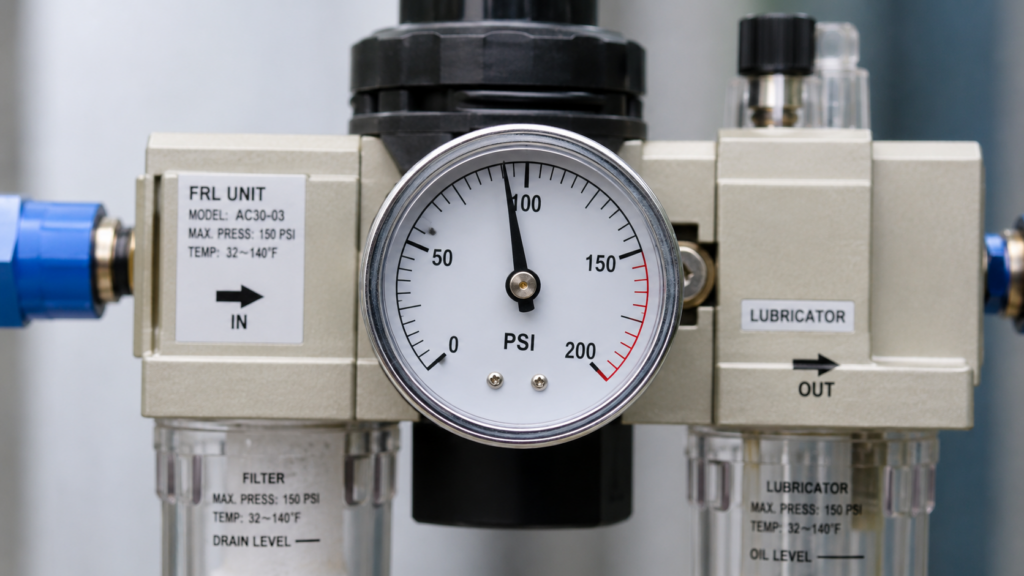
The S-D-R Assessment Model: Reading Beyond The Dial
Observing a gauge needle requires evaluating its movement over time, not just noting a single static number. The S-D-R (Static, Dynamic, Recovery) Assessment Model transforms a basic dial into a predictive maintenance tool for your entire compressed air line. Relying solely on a resting state measurement leads directly to misdiagnosis.
Static Phase: The System Readiness Check
Static pressure reflects the absolute maximum energy available when the system sits idle with zero flow. Mechanics record this baseline PSI reading to confirm the primary air compressor meets the minimum input threshold required by the specific machine. A resting supply pressure that falls below the manufacturer’s specification immediately points to a failing compressor, a faulty primary pressure switch, or a severe upstream main-line rupture.
Dynamic Phase: Exposing Line Restrictions
Dynamic pressure reveals the hidden flow restrictions that static tests mask. The true test of a supply pressure gauge occurs the exact millisecond the heaviest downstream actuators cycle. A massive drop in the supply pressure needle during this actuation phase exposes severely undersized supply lines, clogged filter elements, or malfunctioning isolation valves. You isolate the restriction by comparing the dynamic drop at the machine’s supply gauge to the main compressor’s output gauge; a severe variance confirms a piping issue, not a machine issue.
Recovery Phase: Evaluating Compressor Health
The recovery time indicates the internal volume capacity and compressor regeneration health. Count the seconds it takes for the supply pressure gauge to climb back to its static baseline after an actuation cycle ends. Sluggish needle recovery points directly to excessive moisture accumulation in the receiver tanks reducing volume, or failing compressor reed valves struggling to rebuild head pressure.
Supply Pressure Vs. Output Pressure: The Diagnostic Link
Differentiating upstream and downstream metrics dictates the entire troubleshooting workflow. The supply pressure gauge measures the raw force entering the regulator, while the output (or control) pressure gauge measures the usable force exiting the regulator.
Supply Gauge vs. Output Gauge Diagnostics
| Metric | Supply Gauge Behavior | Output Gauge Behavior | Diagnostic Conclusion |
| Actuation Drop | Drops slightly | Drops heavily | Bad regulator or undersized downstream valve. |
| Pressure Stability | Stable | Fluctuating | Failed regulator diaphragm. |
| Simultaneous Drop | Drops | Drops | Root failure in factory air compressor or facility main air distribution header. |
| Recovery Speed | Sluggish return to static baseline | Slow to reach operating pressure | Excessive moisture accumulation in receiver tanks or failing compressor reed valves. |
A stable supply pressure combined with a fluctuating output pressure pinpoints a failed regulator diaphragm. A dropping supply pressure coupled with a dropping output pressure clears the regulator of fault and redirects your troubleshooting entirely to the facility’s main air distribution header. Misunderstanding this relationship causes technicians to waste hours replacing perfectly functional machine regulators when the factory air compressor is actually the root failure.
Industrial IoT Integration: The Future Of Supply Gauges
Wireless IIoT supply pressure gauges track micro-drops over months to predict catastrophic failures before they cause factory downtime. Modern pneumatic network maintenance abandons analog dial-checking in favor of continuous digital telemetry. Analyzing the historical data logs from a smart supply pressure gauge allows reliability engineers to detect a 0.5 PSI per week degradation. This granular data isolates slow-forming blockages in the facility piping network that manual inspections physically cannot detect.
FAQ
What is the difference between supply pressure and operating pressure?
Supply pressure is the raw, unregulated air force delivered to the machine from the main facility compressor. Operating pressure (or control pressure) is the regulated force actually applied to the actuators or cylinders inside the machine to perform work.
Why does my supply pressure gauge drop when the machine runs?
This indicates a flow restriction or insufficient volume. The supply line diameter might be too small, a primary filter might be clogged, or the main compressor lacks the CFM (Cubic Feet per Minute) capacity to support the machine’s peak demand.
What is a supply pressure gauge used for in an HVAC system?
In pneumatic HVAC control systems, it verifies that the main air compressor is delivering the baseline 20-30 PSI required for the pneumatic thermostats and control valves to function accurately.
How often should an industrial supply pressure gauge be calibrated?
Calibrate critical process supply gauges annually. High-vibration environments or systems handling corrosive gases require semi-annual calibration checks against a certified master gauge to ensure accurate safety limit monitoring.
Can a high supply pressure damage my pneumatic equipment?
Yes. Exceeding the maximum rated input pressure of the primary regulator or filter bowls risks catastrophic physical rupture. The supply gauge serves as the first visual indicator that primary facility regulators have failed open.
Where should a supply pressure gauge be installed?
Install it upstream of the main shut-off valve and the primary FRL (Filter, Regulator, Lubricator) assembly on the specific machine. This placement captures the true facility air condition before any local machine components alter the flow.