 Dypressuregauge

A Venturi Meter Equipped With A Differential Pressure Gauge?
What the differential pressure gauge on the Venturi tube measures and what this system ultimately delivers are two distinct issues. For a venturi meter equipped with a differential pressure gauge, the venturi tube generates a pressure difference related to the flow, the differential pressure gauge measures this difference, and the flow rate is calculated based on the instrument’s characteristics and the fluid properties.
A moving pointer may indicate a change in the pressure difference between the two inputs. How much flow that represents depends on the tapping locations, the conversion relationship, and whether the measurement conditions are valid.
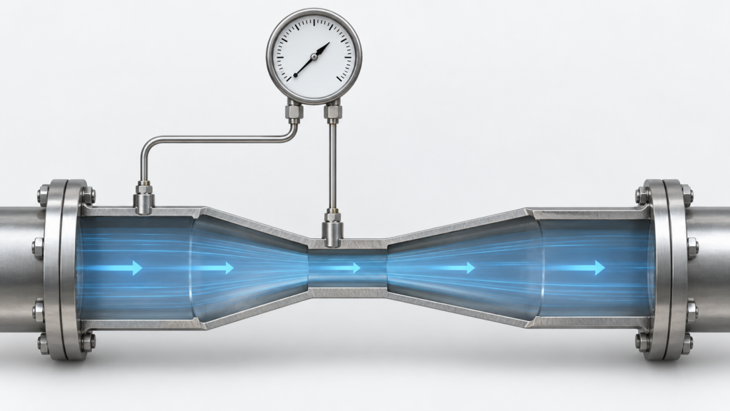
Pressure Tapping Locations Along the Venturi Tube
A typical Venturi tube consists of a converging section, a cylindrical throat, and a diverging section. For a fluid with pressure taps at the same elevation, in steady flow and with negligible density variation, the channel narrows in the contraction section, causing the flow velocity to increase and the static pressure at the throat to decrease relative to the inlet. The pressure difference between the inlet and the throat is the signal utilized in differential pressure measurement.
The pressure taps for a classical Venturi meter are located at the inlet and the throat. Under normal forward flow conditions, the inlet pressure tap is connected to the H terminal of the differential pressure gauge, and the throat pressure tap is connected to the L terminal. The specific pressure-tapping configuration and locations shall be as specified in the Venturi tube design documentation. The differential pressure gauge simultaneously receives two pressure inputs and displays Δp = pH − pL.
After the throat, the diffuser gradually decelerates the fluid, allowing a partial recovery of pressure. Therefore, the differential pressure measured at the inlet–throat is not the same quantity as the permanent pressure loss across the entire device. Pressure recovery does not imply zero energy loss, nor does it mean there is no measurable pressure drop between the inlet and the throat.
Precisely because the pressure recovers downstream, low-pressure connections should not be arbitrarily relocated far downstream. After such a relocation, the measured pressure difference changes, and the original conversion relationship established for the inlet-throat differential pressure can no longer be directly applied. “Low-pressure side” refers to the design-specified low-pressure measurement point, not any downstream location along the pipeline.
Using Differential Pressure to Understand Flow Changes
Under conditions where the Venturi tube remains the same, the fluid density is essentially constant, and the discharge coefficient can be considered unchanged, the flow rate is proportional to the square root of the differential pressure.
Using a hypothetical example that illustrates only the proportional relationship: the reference flow rate is 100 per cent and the reference differential pressure is also recorded as 100 per cent. When the flow rate drops to 50%, the differential pressure is approximately 25% of the reference value; when the flow rate drops to 25%, the differential pressure is approximately 6.25%. Conversely, when the differential pressure is 50% of the reference value, the flow rate is approximately 70.7% of the reference flow rate. These figures are derived mathematically based on a square-root relationship; they do not represent product test results or range recommendations.
Why Low-Flow Readings Are More Difficult
A differential pressure change from 25% to 6.25% also highlights the challenges in the low-flow region: as flow decreases, the differential pressure drops even more rapidly. When differential pressure readings have similar absolute errors, the smaller the differential pressure, the greater the proportion of the error relative to the reading. A properly positioned pointer at maximum flow rate is not sufficient to demonstrate reliable measurement at low flow rates.
Subtracting the readings of two ordinary pressure gauges may not necessarily solve this problem. When the pipeline pressure at both ends is high and the difference is small, the error and resolution of the two meters may obscure the small differential pressure being measured. Directly measuring the differential pressure between the two ends is what distinguishes a dedicated differential pressure gauge from separately reading two gauges and then subtracting their readings.
From Pressure Units to a Flow Scale
A dial labeled in kPa or mbar indicates differential pressure; if it displays units for volumetric or mass flow rate, conversion is required. The correspondence depends on the Venturi’s geometric dimensions, the discharge coefficient, and the actual operating conditions; flow rate cannot be determined solely from a single differential-pressure value.
Displays with flow scales shall include conversion factors that are compatible with the corresponding Venturi tubes and fluid conditions. After replacing the throttling device or changing the operating conditions, the original flow scale may no longer be valid. The percentages shown earlier can only help in understanding the trend of change; they cannot replace design calculations or calibration curves.
Volume, Mass, and Density Compensation
Volumetric flow rate represents the volume passing through a given point per unit time, while mass flow rate represents the mass passing through per unit time; the two are related through density. For fluids whose density varies with pressure and temperature, relying on differential-pressure–flow relationships established under fixed operating conditions may lead to deviations. Whether density compensation is employed and which inputs are used should be determined by the actual medium and system design.
In the field of display and signal processing, differential pressure gauges primarily provide local indication, while differential pressure transmitters can convert the pressure difference into a remote transmission signal, with subsequent instruments or processing systems performing the corresponding calculations. These steps serve different functions; the pressure reading alone should not be taken as having completed all flow calculations.
Differential Pressure Range and Static Pressure Rating
The differential pressure range specifies the maximum differential pressure that can be measured between the two ports, while the allowable static pressure or operating pressure indicates the instrument’s ability to withstand pipeline pressure. Even when both end pressures are high and close to each other, the gauge may still display only a small differential. A low reading does not indicate low pipeline pressure, and a differential pressure gauge cannot replace monitoring of system pressure and safety limits.
When selecting options, verify the normal differential pressure and the maximum possible differential pressure against the differential pressure measurement range; also, ensure that the pipeline pressure borne by both ends is within the allowable static pressure or operating pressure. When measuring small differential pressures under high static pressure, the selected model must possess the corresponding operational capabilities, not merely a sufficiently narrow measurement range.
When connecting, disconnecting, or changing the status of a valve manifold, follow the manufacturer’s instructions and site-approved procedures, and isolate and depressurize as required. When full‑line pressure is suddenly applied to only one side, it is not the same as when both sides share the pressure; therefore, a single, generic sequence of operations cannot be used for all differential‑pressure instruments.
Impulse Lines and Operating Conditions
The connection from the pressure tap to the differential pressure gauge can affect pressure transmission. Leaks, kinks, or condensate accumulation in gas impulse lines, as well as air bubbles in liquid impulse lines, can all affect the measurement. Differences in the length, inner diameter, temperature, and layout of the two pipelines can also lead to asynchronous responses or liquid-column errors.
Checking the connection status is a different task from checking the meter’s zero position. Zero-point verification may only be performed when the pressures at both ends are equal and the manufacturer’s conditions are met; the actual process differential pressure must not be set to zero. For any pipeline disassembly or adjustment, isolation and depressurization must still be performed according to procedure; it is prohibited to disconnect one side while the other side remains pressurized.
The Venturi tube itself also has its own range of applicability. The applications specified in ISO 5167-4 pertain to conditions such as full-pipe flow, single-phase fluid, and subsonic flow within the measurement section, and are not applicable to pulsating flow measurements. When using an uncalibrated Venturi tube according to standard procedures, its applicability is still subject to limitations regarding pipe diameter, surface roughness, diameter ratio, and Reynolds number; the other basis for determining its suitability is the calibrated operating range of the device itself. While its shape conforms to the Venturi design, this does not automatically guarantee that it will achieve the measurement performance specified by the relevant standards in any piping system.
When evaluating this configuration, the analysis can be narrowed down to two specific questions: What two locations’ pressure difference does the differential pressure gauge measure? And on what basis is this pressure difference converted into the flow rate under the current operating conditions?