 Dypressuregauge
Differential Pressure Gauge Working: Principle Explained
The working principle of the differential pressure gauge (Differential Pressure Gauge) is that it introduces two different process pressures (high pressure end/P1 and low pressure end/P2) into a sealed internal chamber. The middle of the chamber is separated by a diaphragm, piston or bellows. The physical deformation of the sensitive element-which is driven entirely by the precise mathematical pressure difference between P1 and P2-pushes the internal magnet or mechanical linkage to turn the dial hands. In the actual application of the field, most of the instrument failure is not because of the “P1 minus P2” formula is wrong, but because the engineer in the selection, the internal mechanical drive type and the specific fluid dynamics characteristics of the pipeline confused. If you don’t want to endlessly replace those broken differential pressure gauges, and want to accurately record the internal mechanical structure of the instrument for the next factory project specification, then we must take apart the specific mechanical mechanism of the piston, diaphragm and bellows actuator and make it clear.
P.A.T. Core Mechanism Teardown
On-site technicians often waste hours recalibrating instruments, but the real sticking point is actually mechanical jamming inside the instrument shell. From the point of view of practical physics, you can split the working principle of any differential pressure gauge into 3 independent processes: the P.A.T. model, that is, pressure (Pressure), drive (Actuation) and transmission (Transmission).
Pressure Conduction (Dual Interface System)
The instrument body physically isolates the process media before it touches the sensor. The high-pressure interface connects the upstream fluid (e. g. before the filter or orifice plate) and the low-pressure interface connects the downstream fluid. It must be kept in mind that the meter housing is subjected to the total static pressure of the entire system, not just that little pressure difference. Once the pressure guide pipe on the low pressure side is blocked, this differential pressure gauge will immediately become an ordinary pressure gauge, not only the pointer will be filled directly, but also the maximum scale will be crossed.
Drive Element: Diaphragm And Piston Duel
Sensitive components take on the core of the hard work. Whether to choose the diaphragm or the piston directly determines the overall service life of this instrument.
Diaphragm drive (for high sensitivity needs and clean media)
The corrugated rubber or metal diaphragm completely isolates the high and low pressure chamber on a physical level. The higher pressure will cause the diaphragm to bend to the low pressure side, and the exact distance the diaphragm moves corresponds to a specific differential pressure value. Diaphragm type differential pressure gauge can completely cut off the cross mixing of fluid, so that the clean environment and contaminated upstream medium to maintain strict separation. They cope well with slight pressure spikes, but if the system overpressure exceeds the burst limit of the diaphragm, the diaphragm will rupture catastrophically.
Piston drive (for severe, high hydrostatic conditions)
The precision machined piston slides back and forth in the cylindrical bore and interacts with a calibrated span spring. The high pressure pushes the piston to one side, while the low pressure and the spring force push it back. Piston-type differential pressure gauges perform particularly well in liquids that withstand very high static pressures (up to 10,000 PSI) and severe pressure spikes. But its physical limitation is “bypass leakage”. The design allows a very small amount of fluid to bypass the piston seal to lubricate the cylinder. Therefore, for fluids with completely different properties, or strictly sanitary pipelines that absolutely prohibit cross-contamination, do not use piston differential pressure meters.
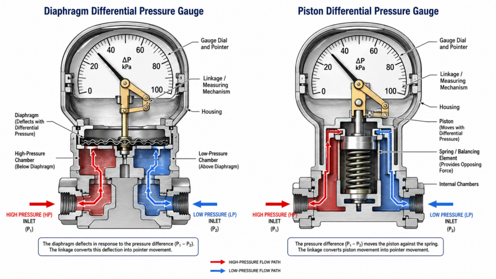
Transmission Structure: Mechanical Linkage And Magnetic Coupling
Once the sensitive element is displaced, the instrument needs to convert this linear motion into the rotary motion of the pointer.
Magnetic coupling (no friction)
A magnet is mounted directly on the moving diaphragm or piston. Outside the pressure boundary is a rotating pointer hub with another matching magnet. When the internal magnet moves laterally, the external magnet will also rotate to keep the magnetic field aligned, thereby driving the pointer. This design does not need to punch holes in the pressure chamber, which fundamentally eliminates the risk of leakage of the process medium.
mechanical rack and pinion drive
1 solid push rod connects the sensitive element with the gear mechanism. The linear thrust of the push rod will drive the pinion connected to the dial shaft to rotate. The mechanical linkage can provide a lot of torque, enough to drive a heavier pointer or micro switch. However, the hole through which the push rod passes out of the pressure chamber must be sealed with a rubber O-ring. After thousands of working cycles, these O-rings will gradually wear out and become a well-known leak point.
| Actuation Type | Best Media | Sensitivity | Fluid Crossover Risk | Max Static Pressure |
| Magnetic Coupling | Strict containment media (Prevents process leaks entirely) | High (Frictionless movement) | None (Eliminates physical holes in the pressure chamber) | Higher (Unrestricted by seals; relies on a solid pressure boundary) |
| Mechanical Rack and Pinion | Standard media (Where potential leaks over time are acceptable) | Lower (Physical linkage friction, but offers high torque for heavy pointers) | High (Known leak path as elastomeric O-rings wear out over cycles) | Limited (Constrained by the elastomeric O-ring seal integrity) |
Hidden Trap: Confusion of System Static Pressure and Differential Pressure
Engineers often break new watches during installation because they misunderstand the concept of static pressure. The working principle of the differential pressure gauge does depend on the pressure difference, but its internal shell is subjected to the actual total pressure of the pipeline.
Imagine a water pipe with a working pressure of 1,000 PSI. The pressure before the filter is 1,000 PSI(P1) and the pressure after the filter is 990 PSI(P2). The differential pressure at this point is only 10 PSI, and the meter pointer will naturally point to 10 PSI. However, the housing inside the instrument and the O-ring of the low-voltage interface are now fighting a huge physical storm of up to 990 PSI. If the low-pressure balance valve is accidentally opened during debugging, the pressure of 1,000 PSI will unilaterally rush to the low-pressure side, instantly smashing the internal mechanical structure. Therefore, it is important to develop the habit of checking the maximum working pressure (MWP) level marked on the dial, which is completely different from the differential pressure scale.
Real Cases in the Field: Diagnosis of “Pointer Slow”
In an on-site audit of petrochemical filter skid-mounted equipment, the maintenance team reported that although the filter element had been completely blocked, the readings of three consecutive piston differential pressure gauges were all 0 PSID.
We disassembled the meter and found the real sticking point. The process fluid contains high viscosity particulate matter. The tiny gap between the piston and the cylinder bore used for bypass lubrication is tightly blocked by solid debris, causing the piston to be directly physically stuck. The mechanical range spring can no longer counterbalance the thrust of the high-pressure side.
Solution: We replaced these piston meters with corrugated metal film differential pressure meters with chemical seals and capillaries. The diaphragm completely blocked the particulate matter from the main body of the instrument, and the failure rate immediately dropped to zero. The core lesson of this case is that it is not only the pressure range that determines the selection of the internal mechanical structure, but also the fluid dynamics.
Frequently Asked Questions (FAQs)
How To Read The Differential Pressure Gauge?
Just read the specific value indicated by the pointer on the dial directly. This value represents the mathematical difference between the high pressure end and the low pressure end. If the high pressure port is 50 psi and the low pressure port is 40 psi, the dial hands will point directly to 10 psi. You don’t need to press the calculator yourself, the internal mechanical structure has already done the subtraction for you through physical means.
What Is The Difference Between Ordinary Pressure Gauge And Differential Pressure Gauge?
The standard pressure gauge has only one connection port, which is based on atmospheric pressure (ambient air) to measure the pressure. The differential pressure gauge has two independent connection ports, which measure the pressure of one process variable relative to another process variable, completely eliminating the interference of atmospheric pressure.
Why Do Differential Pressure Gauges Need To Be Pressure Balanced?
The role of the balancing valve is to prevent unilateral overpressure when the equipment is started or stopped. Open the three-valve group or five-valve group to allow fluid to enter the high and low pressure ports at the same time. This ensures that the differential pressure experienced by the sensitive element is exactly zero, while allowing the entire instrument housing to slowly adapt to the high static pressure of the system.
Differential Pressure Gauge Can Measure Negative Pressure (Vacuum)?
Yes. If the physical pressure applied at the low-pressure end (P2) is higher than that at the high-pressure end (P1), or the high-pressure end bears a stronger vacuum than that at the low-pressure end, the pointer of the differential pressure gauge with the “zero center” design will swing to the negative scale. This requires the use of 1 special dial, its “zero point” calibration in the center of the dial, rather than in the leftmost edge.
Why Does The Differential Pressure Gauge Read Zero When There Is Fluid Flow In The System?
If the reading is zero in the active state of the fluid, it usually means that one of the following three conditions has occurred: the internal diaphragm is broken, the balance valve on the valve block is not closed, or the magnetic connecting rod has completely broken. The test method is to isolate the instrument, evacuate both ports to the atmosphere, and then apply controlled air pressure to the high pressure port. If the pointer still does not move at this time, it means that the internal transmission mechanism has been completely scrapped.