 Dypressuregauge
How Differential & Magnehelic Pressure Gauges Truly Work
The core principle of the differential pressure gauge is actually very straightforward: the specific difference between two different pressure areas is measured through the extremely sharp diaphragm inside. The Magnehelic (magnetic spiral) differential pressure gauge does the same job, but it plays a trick-a magnetic field-driven spiral tube replaces the traditional mechanical transmission and completely clears the physical friction. As for the Photohelic (photoelectric) differential pressure gauge, a photoelectric switch is installed on the basis of this magnetic system, which can directly link the HVAC (heating, ventilation and air conditioning) system for automatic response. In contrast, the refrigerant manifold meters commonly used by air conditioners take another path. They do not need diaphragms, but use extremely pressure-resistant Borden tubes (Bourdon tubes) to pulse the working conditions of the refrigerant.
To be honest, the on-site instruments are broken, mostly not because of poor workmanship of the manufacturers. The real reason often lies in the operation details: for example, the master connected the static pressure pipe to the wrong position, did not take the strong pulse of air flow seriously, or simply did not understand the bearing limit of the internal mechanical structure. Today, let’s directly “pull open” the shells of these precision instruments to see what the underlying design is supporting their accuracy.
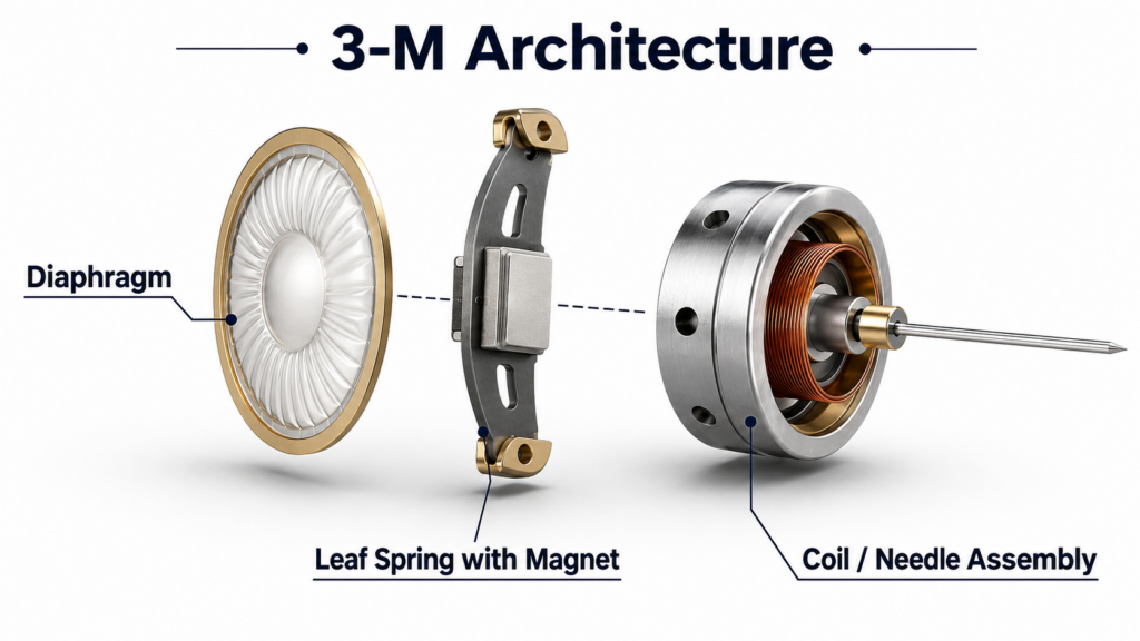
“3-M” Underlying Logic Of Low Voltage Diagnosis
All HVAC measurement tools for low-pressure environments cannot run 3 a continuous physical response. I used to call it a “3-M” framework. As long as you understand this sequence and do troubleshooting on site later, you can see at a glance where the watch is stuck.
- Membrane (induction diaphragm): high-pressure airflow from one port, low-pressure airflow from another port. The pressure difference between the two sides will force the middle layer of silicone rubber diaphragm to push out a bulge on the low pressure side.
- Magnetics/Mechanics (transmission hub): 1 the diaphragm is raised, it will push the 1 adjusted leaf spring. A miniature magnet is fixed to the leaf spring, which will move proportionally.
- Measurement (numerical output): When the magnet moves, the magnetic spiral tube above immediately senses it and rotates accordingly, thus drawing a specific reading with the pointer on the dial.
How Does An Ordinary Differential Pressure Gauge Work?
Air resistance can’t be touched, but the differential pressure gauge can “arm-wrestle” two airflows across a barrier in a sealed chamber, thus transforming it into real data. During normal testing, you connect the high-pressure terminal to the windward side of the component (such as HEPA high-efficiency filter) and the low-pressure terminal to the leeward side.
The “heart” of this watch is the completely airtight flexible diaphragm in the middle of the chamber. When the upstream filter is blocked with dust, the static pressure will soar at the high pressure end, and this accumulated force will actually push the diaphragm. Then, the internal mechanical linkage will capture this micron-scale deformation and increase it into the rotation of the dial hands.
At ordinary times, when teachers use pitot tubes to measure wind speed grid in air ducts, they rely on this mechanical mechanism-the total pressure is automatically subtracted from static pressure inside the instrument, and the dynamic pressure value is directly thrown on the dial.
What Is The Mystery Of Magnehelic (Magnetic Spiral) Differential Pressure Gauge?
Want to achieve extremely high sensitivity without wear? The Magnehelic solution is quite simple: directly “cut” the physical connection between the pressure sensor and the visual display “. It does not use gear sets or levers, but purely relies on an invisible magnetic field to turn the pointer.
When the internal diaphragm is compressed and bent, it will press 1 cantilever leaf spring, and the edge of the leaf spring is accompanied by a miniature magnet with extremely strong attraction. And just above the magnet, there are 1 “spiral tubes” (actually a twisted piece of high-permeability steel) connected to the needle jewel bearing.
When the magnet on the leaf spring moves back and forth, its magnetic field will “bite” the twisted edge of the spiral tube. In order to maintain alignment with the moving magnetic field, the spiral tube can only be forced to rotate, and the needle will rotate. It is precisely because the magnet and the spiral tube are suspended and have no contact at all, so not only absolutely zero friction and zero mechanical loss are achieved, but also the phenomenon of reading hysteresis (Hysteresis) is completely eliminated.
On-Site Real Feedback: Clean Room Filter Aging Monitoring
Mark T., an expert in clean room certification for 15 years, summed it up this way:
“The current digital MEMS sensors do work well, but we still require a purely mechanical Magnehelic pressure differential gauge as standard on the wall of an ISO 5 clean room. The reason is simple: this thing does not need wiring, it works even if the whole plant is powered off, and the operator can 1 look up to confirm that the room is holding positive pressure. As soon as the pointer 1 off, we know that the door must be open or the blower is out of order.”
The Working Principle Of Photohelic (Photoelectric) Differential Pressure Gauge
Photohelic is not just a meter to see, it is more like an automatic control switch. In the original magnetic spiral design, it is inserted into the photoelectric sensor, which perfectly replaces the previous mechanical relay that is easy to jam or spark.
Behind the conventional analog dial, it hides two phototransistors and a light source. You can set the high and low pressure alarm lines by toggling two marks on the front of the dial. These two markers actually act as physical baffles.
Once the actual pressure pointer touches the red line you set, the small baffle attached to the pointer will instantly cut off the beam shining on the phototransistor. The light is 1 broken and the internal solid state relay is triggered immediately. HVAC engineers use this extremely accurate optical trigger mechanism to automatically start the exhaust fan, open the VAV (variable air volume) air valve, or directly sound the alarm when the filter screen is blocked.
How Does The Refrigerant Manifold Table Resist Pressure?
The high temperature and high pressure liquid and gaseous refrigerants in the refrigeration system are quite “irritable. Therefore, the manifold table directly abandoned the fragile diaphragm and replaced it with an extremely leather-like Bunden tube (Bourdon tube). Whether it is repairing air conditioners or dry and cold storage, the masters rely on this heavy instrument to feel the pulse of the entire thermodynamic cycle system of the compressor.
The Baudon tube is actually 1 flattened, crimped metal tube hidden in the case. When the high-pressure refrigerant rushes into the tube, the strong internal pressure will try to “round” and “straighten” the coiled metal tube “. This physical stretching action pulls on the internal gear set, which sweeps the pointer.
Generally, the blue gauge (low pressure side) is responsible for measuring the suction pressure, and can also read the deep negative pressure when the system is vacuumed. The red meter (high pressure side) is specially used to knock the extreme high pressure discharged by the compressor.
Pressure Gauge Technology Matrix
| Gauge Type | Sensor Mechanism | Typical Range | Primary HVAC Use Case | Vulnerability |
| Standard Differential | Flexible diaphragm or bellows | Low to medium pressure (e.g., inches of water column) | Measuring pressure drops across air filters, coils, and ductwork | Delicate diaphragm is highly susceptible to overpressure ruptures and spikes |
| Magnehelic | Silicone diaphragm with frictionless magnetic linkage | Very low pressure (e.g., 0-5 in. w.c.) | Monitoring building static pressure, clean rooms, and filter resistance | Heavy vibration or physical shock can disrupt the sensitive magnetic movement |
| Photohelic | Diaphragm with magnetic linkage and built-in optical switches | Very low pressure (e.g., 0-5 in. w.c.) | Automated fan/damper control and activating high/low pressure alarms | Dust interfering with optical sensors (phototransistors) or electrical failure |
| Manifold | Robust Bourdon tube (flattened, coiled metal pipe) with gear linkage | Deep vacuums (suction) to extreme high-pressure liquid/gas states (discharge) | Diagnosing the entire thermodynamic cycle of a compressor in refrigeration systems | Mechanical wear, physical drops, or shock damage to the internal gear linkage |
The Old Mage’s Guide To Avoiding Pits: Don’t Make These Mistakes.
Experienced veterans all know that it is often not the daily operation that destroys the instrument, but the exotic working conditions on site. Whether it is installation or obstacle removal, the following 3 pits must be avoided:
- Condensate trap: If you pull the pressure hose up from the cold water coil and connect it to the differential pressure gauge, you have essentially built your own “reservoir”. Condensate flows back into the table along the tube. Once it floods the diaphragm cavity, the calibration of the table is completely useless. Remember that the table must be positioned higher than the measuring point and the tube must be tilted downwards.
- Direct airflow pulsation “headshot”: If you take a highly sensitive Magnehelic meter and directly press it against the extremely violent air outlet of a high-speed centrifugal fan, the needle will definitely shake wildly. This high-frequency vibration can hard break the gem bearing inside. In this case, be sure to string a buffer (porous metal flow restrictor) on the pipeline to pulse “flatten” the air flow before entering the meter.
- Overpressure burst: This watch would have only been able to withstand a 2-inch column of water (in. wc) For the micro-pressure, you have to take 100 PSI of workshop compressed air to “purge” the static pressure pipe while the meter is still connected. As a result, the silicone diaphragm will explode on the spot. When the pressure measuring tube is connected to the meter, it is absolutely prohibited to use a high-pressure air gun to blow.
FAQ (Often Asked By Peers)
Can a differential pressure gauge measure vacuum (negative pressure)?
Of course you can. You just connect the system to the low-pressure port of the watch and open the high-pressure port directly to the atmosphere, and the dial can read the negative pressure value (that is, vacuum degree) of the system very accurately.
Why doesn’t my Magnehelic table return to zero?
This is usually because the watch is not flat or has previously suffered a severe overpressure shock. This table must guarantee an absolutely vertical installation. You can reset it to zero with the adjustment screw at the bottom of the panel, but if it goes off the rails without moving, it basically means the leaf spring inside has undergone a permanent physical deformation and is hopeless.
What is the difference between static pressure and pressure difference?
Static pressure refers to the resistance of the air in the duct to push outward against the duct wall. The pressure difference is simply the mathematical difference between the static pressure values you measure at two different locations and the two when subtracted.
Can I get a Magnehelic meter to test for liquids?
Don’t. Standard Magnehelic surfaces are designed for air and non-corrosive gases. Once water or oil enters the interface, the silicone diaphragm and magnetic transmission system inside will be scrapped immediately. The test liquid must be fed a special “wet-on-wet” (wet/wet) differential pressure transmitter.
How often does the Photohelic (photoelectric) differential pressure gauge need to be calibrated?
If it is a critical place such as a pharmaceutical dust-free room or an isolation ward, the industry has mandated one school per year. For ordinary commercial air conditioning projects, calibration is usually only required every two or three years, depending on the dust volume and vibration conditions on site.
Why do the outer and inner rings of a refrigerant manifold gauge have different temperature scales?
This is because the refrigerant table is to directly show the temperature relationship of a specific refrigerant (such as R-410A or R-134a) at a specific pressure. The outer ring reads the pressure value, and the inner ring corresponds to the saturation temperature of the chemical at the current pressure. With this scale, when the masters calculate the superheat and supercooling degrees on site, they don’t even need to check the conversion table, which is clear at a glance.