How Does A Pressure Transmitter Work
The core task of a pressure transmitter is to convert the physical mechanical force into a standardized electrical signal. This process follows a very rigorous “three-step” logic: first, “process pressure” acts directly on the sensing element; then, this force causes extremely small physical deformations that change certain electrical properties; finally, The electronic modules and sensors inside the transmitter process this original change into a linear, proportional signal that can be read by the PLC or DCS system. In those high-load operating environments, whether monitoring liquids, gases or steam, this mechanism is to ensure system safety and operating efficiency.
Process Pressure And “Intimate Contact With” Sensing Elements
The entire measurement process starts from the contact point between the industrial medium and the meter. We are going to talk about the working principle of the transmitter, and the first thing to look at must be the sensing element.
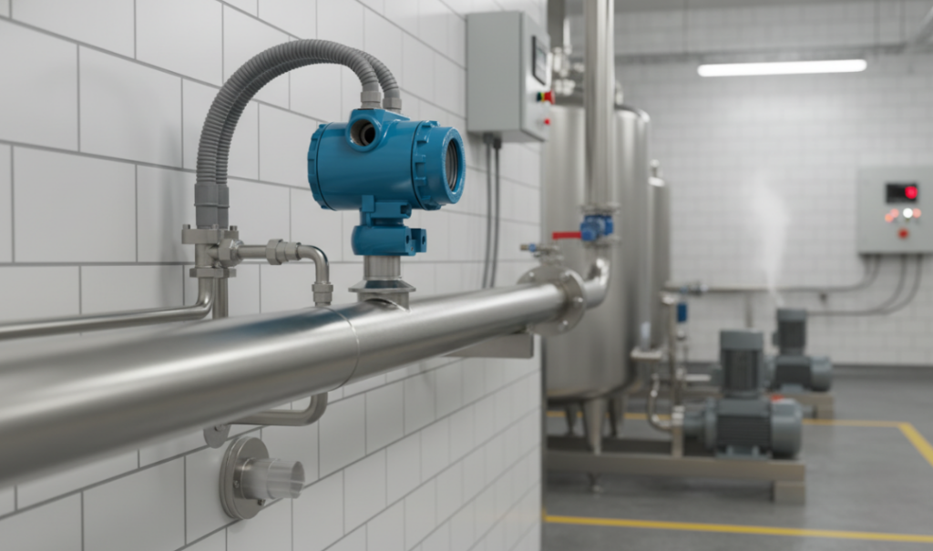
Field maintenance engineers must maintain a high level of attention to the diaphragm. Depending on the application scenario, this diaphragm is usually made of 316L stainless steel, Hastelloy C or ceramic. When process pressure is pressed over, the diaphragm acts like a flexible barrier.
Choosing the right materials at this stage is a life-saving matter. If the medium and diaphragm materials do not match, corrosion or the so-called “hydrogen seepage” phenomenon will quickly result, which will cause serious signal drift ——which is the most troublesome and difficult problem for maintenance teams to check. Ultimately, the physical displacement generated here is the “original input” that drives the entire measurement chain.
Energy Conversion —— The Transition From Mechanical Deformation To Electrical Signal
Once the pressure has lifted the diaphragm, the next step is the complex energy conversion process, which we often call the “sensing” process. Those tiny deformations that occur on the diaphragm that are invisible to the naked eye are captured by sensors directly bound to it.
There are two main technologies currently on the market:
Piezoresistive sensor: It utilizes the strain gauge principle. When the strain gauge is stretched or compressed with the diaphragm, its resistance value changes. This resistance change is directly proportional to the pressure felt.
Capacitive sensor: In this structure, the sensing diaphragm is located between two fixed capacitive plates. Displacement of the diaphragm changes the capacitance value of the circuit. I personally prefer to use capacitive type in situations where high precision and low voltage range are required. Its sensitivity and long-term stability are indeed more advantageous.
This stage directly determines the “accuracy” and “reproducibility” of the transmitter, which are the two most core technical indicators when comparing different brand numbers in procurement.
Signal Conditioning And Normalized Output
This last step is the key to explaining how those weak, messy raw electrical signals become “useful data”. The electronic wiring board inside the transmitter performs several key operations on nonlinear signals from the sensor:
- Linearization: Correct the original sensor data to a linear relationship that exactly corresponds to the pressure range.
- Temperature compensation: After all, the ambient temperature in the field jumps wildly, and the circuit must correct the measurement errors caused by temperature drift in real time.
- Scaling: Accurately maps pressure ranges to standard electrical signals.
From a maintenance perspective, the 4-20mA current ring is simply a masterpiece of industry. Not only is it highly resistant to interference and suitable for long-distance transmission, it also provides a “live zero” function ——if the current goes straight to zero, you can tell at a glance that the line is broken, not that the pressure has actually reached zero. Today’s smart transmitters usually also have the HART protocol superimposed on them, allowing us to remotely tune and diagnose while sitting in the control room, saving us a lot of trouble climbing cans.
Author: Robert Chen
My career has been spent navigating the complexities of process control, from troubleshooting stubborn sensors in the middle of a plant to advising procurement teams on large-scale hardware integration. I specialize in translating intricate technical mechanisms into practical, actionable insights to help maintenance engineers and site managers optimize system reliability and reduce operational costs.