How To Check Pressure Transmitter With Multimeter
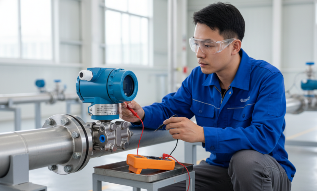
First, dial the multimeter to the DC milliampere position and confirm that the red watch pen is plugged into the “mA” jack. This step is not done correctly and all the work is wasted. For a standard two-wire transmitter, you have to disconnect the circuit and string the multimeter in: the red pen connects to the positive wire from the 24V DC circuit power supply, and the black pen connects to the positive terminal of the transmitter. At zero process pressure, the multimeter should accurately display 4.00 mA. Next, pressurize to full-scale rated pressure using a portable pressure pump, and the reading should reach 20.00 mA. This step of testing can directly verify the linearity of the transmitter, capture sensor drift, and confirm whether the analog output signal is complete, eliminating the trouble of disassembling the equipment back into the laboratory. If the reading is 0.00 mA, don’t jump to conclusions just yet and check to see if the multimeter’s fuse is blown or the power is out.
Understanding 4-20mA Current Loop Configurations
When trying to figure out how to use a multimeter to measure a transmitter, the most important concept is “series connection”. This is completely different from measuring voltage, which is connected in parallel, but the 4-20mA loop requires that the multimeter must be part of the circuit. It’s about letting current flow through the multimeter so you can measure the actual electron flow modulated by the pressure transmitter.
The signal output of this type of transmitter is very stable in extremely harsh industrial environments, which makes the troubleshooting work of on-site maintenance technicians very intuitive and will not be interfered with by random signals.
Measuring The mA Signal
Before moving the line, adjust the tools. This is the basic skill:
Mode selection: Turn the knob to DC mA.
Pen position: Move the red pen to the mA input jack. It is common to see people on site using the voltage hole to measure the current, and the result is definitely zero reading. If not, it will burn the internal fuse of the multimeter.
To measure the current signal, the circuit must be in the “disconnected” state. In a typical two-line setup:
Find the positive terminal post at the transmitter end, or the corresponding wire in the terminal box.
Remove this wire and create an open circuit.
Connect the multimeter’s red watch pen to this wire coming out of the 24V DC circuit power supply.
Attach the multimeter’s black watch pen to the positive terminal of the transmitter.
After connecting the line, observe the change in value:
Zero Check: When the transmitter is ventilated to atmosphere, the DMM should display 4.00 mA. Any significant deviation indicates that the sensor is drifting and may need to be retuned.
Full Scale Check: Use a portable pressure pump to pressurize to the highest rated pressure of the device. At this point the DMM should accurately display 20.00 mA.
Linearity And Signal Integrity

The ultimate goal of checking a transmitter is to verify its linearity. According to the empirical formula, if you apply 50% of the rated pressure, the multimeter should ideally show 12.00 mA.
Linear verification: If the signal jumps or freezes, it usually means that the internal sensing element or circuit board is about to “hang”.
Analog output signal integrity: A stable, non-fluctuating reading demonstrates that the transmitter is effectively converting physical pressure into electrical signals.
What If The Reading Is 0.00 mA
If the multimeter shows 0.00 mA in the test, it usually points to these two old-fashioned questions:
Multimeter fuse blown: This is all too common. Most of them were caused by mis-testing the voltage with the mA gear before. Before concluding that the transmitter is broken, test the meter to see if it is broken.
Power Failure: Check that the 24V DC loop power supply is normal. If there is no power, the transmitter cannot modulate the loop current at all.
Author: Robert Miller
Throughout my career, I’ve diagnosed and calibrated thousands of control loops in high-pressure environments. I am passionate about sharing practical, field-tested troubleshooting techniques that help maintenance technicians work more efficiently. I write to bridge the gap between complex engineering theory and real-world application to ensure industrial safety and minimize downtime.